UTR1 Cogeneration Series
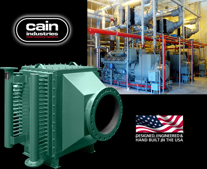
U-Tube Recovery 1
For Large Engine and Compact Design
The UTR1 is applied primarily where confined area restrictions vs. heat transfer requirements must be considered as a priority to the combined features of the HRSR. Its compact industrial design allows for maximum BTU recovery relative to the space allotted for installation. Finned tube spacings range from bare tube heating surface up through 8 fins per inch, depending on the fouling factor requirements. Standard fin to tube attachment using the nickel braze/weld fin to tube process allows no fin to tube separation to 2,000°F.
The UTR1 can be located above the engine or on the floor for convenient installation. With over 170 standard configurations to choose from, the UTR1 can be designed to meet the closest pinch point requirements when installation space is not an issue. Easy access allows for quick removal of finned tube rows or core assemblies without disturbing the exhaust gas connections and allows for routine inspections and/or cleaning requirements.
Engine Exhaust Application
Capacity: 200kW to 10MW
Entering gas temps: up to 1,600°F
Heat Sink Types: process water, boiler feedwater, ethylene glycol or thermal transfer fluids
- Parallel piping flow arrangement for high liquid flow.
- Series piping flow arrangement
- Fin tube rack assemblies (spaced for accessible cleaning)
– Tube materials: carbon steel, TP316 stainless
– Fin materials: carbon steel, TP304, aluminum
– Methods of finned tube attachment: nickel brazed, Al-Fuse™ and welded - Factory insulation (optional): 2" to 6" thickness available
- Inspection door for accessing fin tubes
- Inspection door (optional) for heating surface cleaning
- 10 ga. carbon steel seal welded exterior
- 3/4" NPT vent
- ASME stamp (optional)
- Lifting lugs
- Exhaust transition (optional)
- 3/4" NPT drain
- H-Beam support
- 1-1/2" NPT condensate cleanout drain (optional)
- Inspection doors for easy access and cleaning
- Exterior exhaust gas bypass and actuator assemblies
- Exhaust piping to UTR1 transitions
- Rotating sootblowers (automatic or manual)
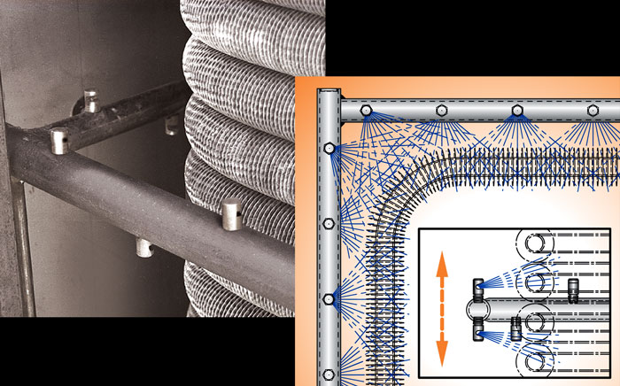
Automatic or Manual Sootblower (optional)
The exclusive Cain Industries Timed Automatic Sootblower design is applied to combustion sources where the sulfur content is high and/or combustion efficiency is poor. When a soot layer accumulates on the heating surface to a thickness of 1/8", fuel consumption is increased by 8.5%. The sootblower is also applied when it is not cost-effective to open inspection doors and clean the exchanger by other means. The sootblower system will continually keep the heating surface at a high performance level and eliminate the day-to-day operator expense and engine down time.
The blowdown sequence occurs while the engine is in full operation and is fully adjustable. The special flood-jet type nozzles achieve maximum cleaning velocity using steam or air as discharged through an electric control valve (included). Together they form a "continuous knife edge concentrated spray pattern" surrounding the heating surface. This "ring nozzle assembly" as attached to a manifolded flexible steel hose assembly, is powered up and down by a pneumatic drive cylinder. Dual timing relays allow complete control for 30 second cycle duration and intervals specific to each application. Final results are controlled double cleaning action, insuring that the maximum BTU recovery and anticipated savings are achieved.